how to draw a number 11 in 3d
I am an online author who enjoys writing about mathematics and science.
Canva
In this commodity we will run into how to draw a two-dimensional representation of a four-dimensional object.
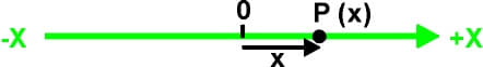
Fig. ane. The number line showing 1D infinite
Fig. 1 shows the x-axis or number line. This is a single dimension. Any point on the line is represented by a single number (+x or -ten) that indicates its distance from the origin (0).
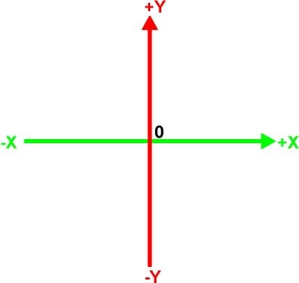
Fig. ii. Ten and Y axes of 2D space
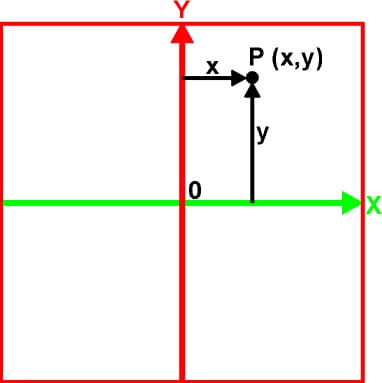
Fig. 3. One plane of 2D space
Fig. 3 shows the x,y plane, indicted past a square that contains the x,y axes of 2D infinite. These axes are 90 degrees to each other. Whatsoever signal on the plane is located by ii numbers (x,y). X is the distance from the y-axis to the point. Y is the altitude from the x-axis to the point. The 2D coordinate system is a single plane.
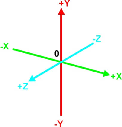
Fig. iv. The X, Y, and Z axes of 3D space
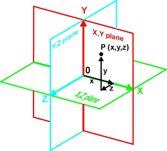
Fig. five. The three planes of 3D space.
Whatsoever point in 3D space is located by three numbers (x,y,z). The 3D coordinate system consists of iii planes. Here these planes are indicated past squares and they are each 90 degrees to each other. Because we are viewing the planes at an angle and their image is flattened to the 2nd surface of the page, the squares exercise not look like squares and the angles do non announced to be ninety degrees. However, we are used to seeing squares at an angle and can accept the drawing equally representing three perpendicular squares.
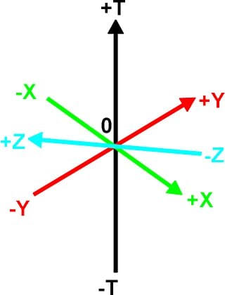
Fig. 6. The four mutually perpendicular axes of 4D infinite. These can represent three spatial axes and one time axis or four spatial axes x,y,z,westward
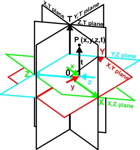
Fig. 7. The three 3D planes on their 4D axes.
The 4D coordinate system consists of six planes. This equals all the paired combinations of the axes, xy, xz, xw, yw, zw and yz. That is the number of combinations of due north objects taken r at a time = north!/r!(n-r)! = 4!/two!(iv-2)! = 24/4 = 6.
Just as the 3D planes appear distorted when projected on a 2D surface, these planes in 4 dimensions are even more than distorted when projected on a 2d surface. Fig. vii shows the 2d projection of the six planes that described 4D space. Any point in 4D space is located by four numbers (x,y,z,t). A representation of 4D space is similar a time-exposed photo since each 3D department occurs at a different instant in time. This -D space is the Minkowski space when the Lorentz transformations are used with this coordinate system.
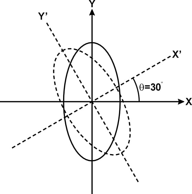
Fig 8. The rotation of a second effigy on a single aeroplane.
Read More From Feltmagnet
In analectic geometry there are two combined equations used for rotating all the 2d points in an object by the angle q, on the ten,y plane. These equations are
x' = x*cos q – y*sin q
and
y' = x*sin q +y*cos q
Using the Equations for the 3D Figure
By expanding these two equations into six equations and using points indicated by three numbers, we produce a 2D representation of a 3D object. When one airplane is rotated the whole figure is rotated by the aforementioned corporeality. By using three different angles of rotation this representation of a three-dimensional object can be viewed from any bending.
Algorithm that produces the 3D effect:
XA=X*COS(A1)-Y*SIN(A1):
YA=X*SIN(A1)+Y*COS(A1)
XB=XA*COS(A2)-Z1*SIN(A2)
ZA=XA*SIN(A2)+Z1*COS(A2)
ZB=ZA*COS(A3)-YA*SIN(A3)
YB=ZA*SIN(A3)+YA*COS(A3)
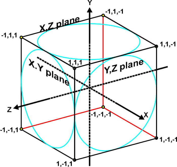
Fig. 9. A cube is a 3D object.
Using the Equations for the 4D Figure
By expanding these two equations into 12 equations and using points indicated by four numbers, nosotros produce a 2D representation of a 4D object. Past rotating any or all of the vi planes of the 4D object, the representation of a 4-dimensional object can be viewed from any angle.
Algorithm that produces 4D prototype:
ZA=Z*CQS(A1)-Westward*SIN(A1)
WA=Z*SIN(A1)+W*COS(A1)
YA=Y*COS(A2)-WA*SIN(A2)
WB=Y*SIN(A2)+WA*COS(A2)
XA=10*COS(A3)-ZA*SIN(A3)
ZB=10*SIN(A3)+ZA*COS(A3)
XB=XA*COS(A4)-WB*SIN(A4)
WC==XA*SIN(A4)+WB*COS(A4)
YB=YA*COS(A5)-ZB*SIN(A5)
ZC=YA*SIN(A5)+ZB*COS(A5) :
Ninety=XB*COS(A6)-YB*SIN(A6)
YC=XB*SIN(A6)+YB*COS(A6)
X2=K*(Xc+Ninety*ZC/800+Xc*WC/800)+158:REM adds perspective to 10(k=scale)
Y2=0.eight*Grand* (YC+YC*ZC/800+YC*WC/800)+100:REM adds perspective to y(grand=scale)
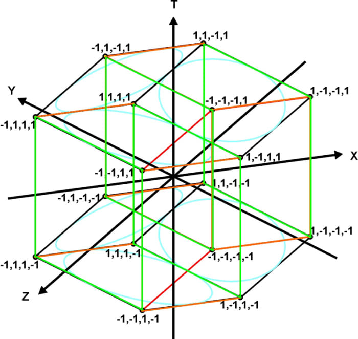
Fig. x. Tesseract or four dimensional hypercube
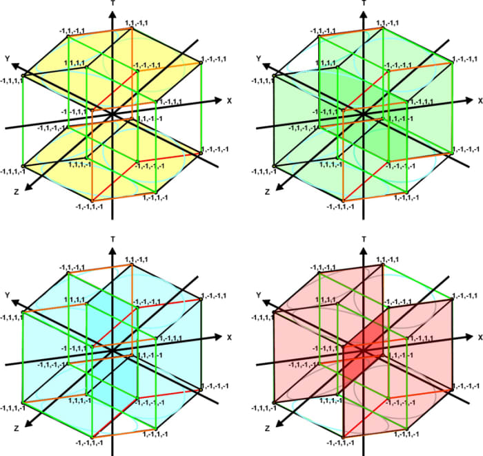
Fig. xi. The hypercube is composed viii interlaced 3D cubes
The Computer Plan 4D-CUBE Draws the Tesseract
This program draws a two-dimensional representation of a 4-dimensional hypercube. Each of the 16 points or vertices are indicated by iv numbers. One number for the x-axis, the y-axis, the z-axis and the w-axis. The 32 edges are indicated by drawing a line betwixt two vertices.
Figs. 12 and xiii testify the hypercube at different degrees of rotation. Fig. 14 shows the hypercube with no rotation around whatsoever centrality. Because the program has a perspective factor in it fig. fourteen appears every bit three connected squares. Without perspective fig. 14 would announced as a single square but as a 3D cube does. In GW Bones the height of the pixels is greater than the width. When figures are viewed on the screen they are taller than they should be. By multiplying the final y past 0.8, these drawings have been adjusted so that the height and the width are proportionally corrected.
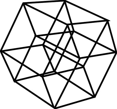
Fig. 12
4D hypercube and the rotation of each plane
ROTATION OF ZW PLANE 10°
ROTATION OF YW PLANE 20°
ROTATION OF XZ PLANE 30°
ROTATION OF XW PLANE xl°
ROTATION OF YZ Airplane 50°
ROTATION OF XY PLANE 60°
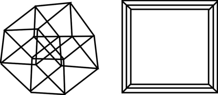
Fig. 13 . . . . . . . . . . . . . . . . . . . . . . . . . . . . . .Fig 14
4D hypercube and rotation of planes . . . 4D hypercube and rotation of planes
ROTATION OF ZW Aeroplane 50° . . . . . . . . ROTATION OF ZW Plane 0°
ROTATION OF YW Airplane 50° . . . . . . . ROTATION OF YW PLANE 0°
ROTATION OF XZ PLANE 50° . . . . . . . . ROTATION OF XZ Plane 0°
ROTATION OF XW PLANE 0° . . . . . . . . ROTATION OF XW PLANE 0°
ROTATION OF YZ Airplane 0° . . . . . . . . ROTATION OF YZ PLANE 0°
ROTATION OF XY Plane 0° . . . . . . . . ROTATION OF XY PLANE 0°
The Computer Program 4D-CUBE in GW Bones
100 CLS:REM 4D-CUBE 110 DIM Ten(300)
120 DIM Y(300)
130 DIM Z(300)
140 DIM West(300)
150 INPUT "Calibration (suggest 1)";Thou
160 INPUT "ROTATION OF ZW Airplane IN DEGREES";Al
170 INPUT"ROTATION OF YW Aeroplane IN DEGREES";A2
180 INPUT "ROTATION OF XZ PLANE INDEGREES";A3
190 INPUT "ROTATION OF XW Plane IN DEGREES";A4
200 INPUT "ROTATION OF YX Airplane IN DEGREES";A5
210 INPUT "ROTATION OF XY PLANE IN DEGREES";A6
230 A1=A1/57.29577951 converts degrees to radians
240 A2=A2/57.29577951
250 A3=A3/57.29577951
260 A4=A4/ 57,29577951
270 A5=A5/57.29577951
280 A6=A6/57.29577951
290 SCREEN ane,0: CLS:Central OFF:Colour 0,1 320 FOR Northward=I TO 2
330 READ X,Y,Z,West:REM reads data
340 IF 10=ane.000 THEN 530
350 ZA=Z*CQS(A1)-W*SIN(A1) :REM Algorithm that produces 4D image
360 WA=Z*SIN(A1)+W*COS(A1)
370 YA=Y*COS(A2)-WA*SIN(A2)
380 WB=Y*SIN(A2)+WA*COS(A2)
390 XA=X*COS(A3)-ZA*SIN(A3)
400 ZB=X*SIN(A3)+ZA*COS(A3)
410 XB=XA*COS(A4)-WB*SIN(A4)
420 WC==XA*SIN(A4)+WB*COS(A4)
430 YB=YA*COS(A5)-ZB*SIN(A5)
440 ZC=YA*SIN(A5)+ZB*COS(A5) :
450 XC=XB*COS(A6)-YB*SIN(A6)
460 YC=XB*SIN(A6)+YB*COS(A6)
470 if n=1 then 540
480 X2=Chiliad*(90+XC*ZC/800+Ninety*WC/800)+158:REM adds perspective to x(k=scale)
490 Y2=0.8*K* (YC+YC*ZC/800+YC*WC/800)+100:REM adds perspective to y(chiliad=calibration)
500 NEXT Due north
505 IF W=40 THEN 1000: REM highlights one 3D cube
510 LINE (X1, Y1)-(X2,Y2),3:REM draws effigy
520 GOTO 320
530 Terminate
540 X1=K* (XC+XC*ZC/800+XC*WC/800)+158:REM adds perspective to x(k=scale)
550 Y1=0.8*Grand*(YC+YC*ZC/800+YC*WC/800)+100:REM adds perspective to y(thou=calibration)
560 GOTO 500
600 DATA -40,-twoscore,twoscore,-40,40,-40,xl,-40
610 DATA -40, -40, twoscore, forty, 40, -40, 40, 40
620 DATA xl,-twoscore,twoscore,-40,xl,twoscore,40,-40
630 Data 40,-40/40,twoscore,xl,40,40,40
640 DATA forty,forty,40,-40,-40„40,xl,-40
650 Information 40,twoscore,40,40,-40,40,40,xl
660 Information -40,40,40,-xl,-twoscore,-forty,forty,-xl
670 Information -xl ,40. 40, 40, -40, -forty, 40, 40
680 Data -40,-40,-xl,-40,40,-forty,-40,-forty
690 DATA -twoscore, -40, -40, xl, 40, -forty, -40, 40
700 Information 40,-40,-40,-40,40,40,-forty,-40
710 DATA forty,-twoscore,-forty, 40, 40, 40,-40, forty
720 DATA 40, 40, -40, -forty, -40, 40, -40, -40
730 Information 40,twoscore,-forty,40,-forty,40,-40,40
740 DATA -40,forty,-twoscore,-40,-40,-xl,-40,-twoscore
750 Information -forty,twoscore,-40,40,-40,-40,-xl,twoscore
760 DATA -40, -40, 40, -40, -40,-xl,-forty,-twoscore
770 Data -xl,-xl,40,40,-40,-40,-40,twoscore
780 DATA 40, -40, 40, -xl, 40, -40, -40, -twoscore
790 DATA 40, -twoscore, 40, 40, 40, -40, -forty, 40
800 DATA 40, 40,40,-40,40,40,-40,-40
810 Information 40,twoscore,40,xl,40,40,-40,forty
820 Data -40,40,40,-40,-twoscore,40,-40,-40
830 Information -twoscore, 40, 40,40, twoscore , 40, -40, 40
840 DATA -40,-40,40,-40,-40,-40,xl,40
850 Data forty,-40,40,-40,xl,-40, 40,xl
860 Data xl,forty,twoscore,-40,40,xl,xl,forty
870 Data -forty,forty,40,-40,-xl,xl,40,40
880 DATA -40,-40,-40,-40,-forty,-xl,-40,40
890 DATA 40,-forty, -40, -twoscore, 40, -xl, -xl, 40
900 Information 40,forty,-forty,-xl,xl,forty,-40,forty
910 DATA -xl,40,-40,-xl,-40, 40,-forty, twoscore
920 DATA 1000,yard,k,grand
chiliad LINE(X1,Y1)-(X2,Y2),2
1010 GOTO 320
The Computer Program 4D-Plane
This program draws a two-dimentional representation of the six planes of the four axes. Fig. 15 shows the six planes and the coordinates in 4D space. A layout like this is helpful before cartoon whatsoever 4D figure. By using six different angles of rotation this representation of four-dimensional planes can be viewed from any angle. When all the angles are at zero nosotros see the 10.y airplane every bit a foursquare. All the other planes are edge-on.
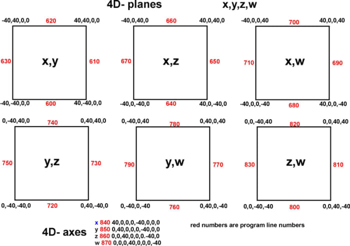
Fig 15. The vi planes of 4D space
Fig. 15 lays out all the points in the 4D coordinate organization. These are used in the computer program 4D-PLANE
In figs. sixteen to 18 we come across 3D planes are drawn with blue lines, while all the planes containing the w-axis are drawn in red. When we run the calculator program the 3D planes are fatigued with white lines while all the planes containing the w-axis are drawn in purple. In GW Basic the height of the pixels is greater than the width. When figures are viewed on the screen they are taller than they should be. By multiplying the final y by 0.8, these drawings accept been adapted so that the height and the width are proportionally corrected.
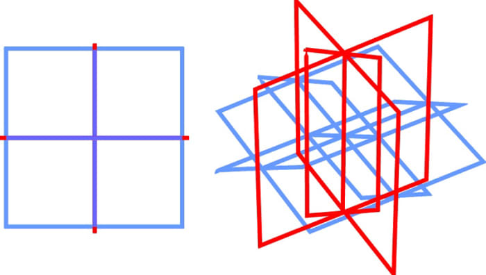
Fig.16. . . . . . . . . . . . . . . . . . . . . . . . . . . . . Fig. 17
4D planes and the rotation of planes 4D planes and the rotation of planes
ROTATION OF ZW Plane 0° . . . . . . . . ROTATION OF ZW PLANE 0°
ROTATION OF YW PLANE 0°. . . . . . . . ROTATION OF YW PLANE 0°
ROTATION OF XZ Plane 0° . . . . . . . . ROTATION OF XZ Aeroplane 30°
ROTATION OF XW PLANE 0° . . . . . . . ROTATION OF XW Plane 50°
ROTATION OF YZ Airplane 0° . . . . . . . .ROTATION OF YZ PLANE lxx°
ROTATION OF XY PLANE 0° . . . . . . . . ROTATION OF XY PLANE 90°
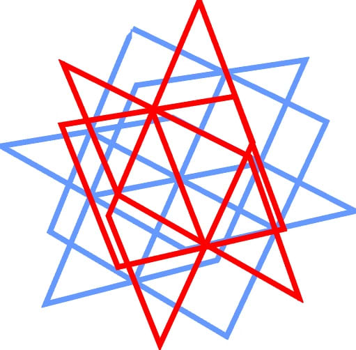
Fig. 18
4D coordinate planes and the rotation of each plane
ROTATION OF ZW PLANE 10°
ROTATION OF YW PLANE 20°
ROTATION OF XZ Plane xxx°
ROTATION OF XW Plane xl°
ROTATION OF YZ Aeroplane 50°
ROTATION OF XY PLANE sixty°
This figure is complex and hard to visualize. To help in the visualization of this figure, fig. nineteen is separated into two parts. Beginning are the 3D planes with the x,y,z axis. Second are the planes containing the west axis.
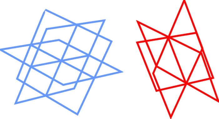
Fig. xix. Two parts of a 4D coordinate system.
Computer Program 4D-PLANE
100 CLS:REM 4D-PLANE
110 DIM XC300) . 120 DIM Y(300) 130 DIM Z(300) 140 DIM West(300) 150 INPUT "SCALE";K
160 INPUT "ROTATION OF ZW Airplane IN DEGREES";Al
170 INPUT "ROTATION OF WY PLANE IN DEGREES";A2
180 INPUT "ROTATION OF XZ Aeroplane IN DEGREES"; A3
190 INPUT "ROTATION OF XW Aeroplane IN DEGREES";A4
200 INPUT "ROTATION OF YZ PLANE IN DEGREES";A5
210 INPUT "ROTATION OF XY Aeroplane IN DEGREES";A6
230 A1=A1/57. 2957795* :REM converts degrees to radians
240 A2=A2/57.29577951*
250 A3 =A3/57. 29577951*
260 A4=A4/57.29577951*
270 A5=A5/57,29577951*
280 A6=A6/57.29577951*
290 SCREEN 1,0:CLS:KEY OFF:Colour 0,1
320 FOR.Due north=1 TO 2
330 READ Ten,Y,Z,W
340 IF X=1000 Then 530
350 ZA=Z*COS(A1)-Westward#SIN(A1):REM algorithms to produce 2D representation of 4D object
360 WA=Z*SIN(A1)+W*COS(A1)
370 YA=Y*COS(A2)-WA*SIN(A2)
380 WB=Y*SIN(A2)+WA*COS(A2)
390 XA=X*COS(A3)-ZA*SIN(A3)
400 ZB=X*SIN(A3)+ZA*COS(A3)
410 XB=XA*COS(A4)-WB*SIN(A4)
420 WC=XA*SIN(A4)+WB*COS(A4)
430 YB=YA*COS(A5)-ZB*SIN(A5)
440 ZC=YA*SIN(A5)+ZB*COS<A5)
450 Xc=XB*COS(A6)-YB*SIN(A6)
460 YC=XB*SIN(A6)+YB*COS(A6)
470 IF N=l THEN 540
480 X2=One thousand*(XC+XC*ZC/800+XC*WC/800)+158
490 Y2=0.8*K*(YC+YC*ZC/800+YC*WC/800)+100
500 NEXT Due north
505 IF W= twoscore OR Due west= -40 So 1000
510 LINE (X1,Y1)-(X2,Y2),3
520 GOTO 320
530 End
540 X1=K*(90+XC*ZC/800+Ninety*WC/800)+158
550 Y1=0.eight*One thousand*(YC+YC*ZC/8OO+YC*WC/800)+100
560 GOTO 500
600 Information - 40,- forty„0,0 , forty,- 40,0,0
610 DATA xl,- forty,0,0,xl,twoscore,0,0
620 DATA 40,40,0,0,-twoscore,xl,0,0
630 Data - 40,40,0,0,- 40,- 40,0,0
640 Information - xl ,0,40, 0, 40, 0., - 40, 0
650 DATA 40, 0,- 40,0,forty,0, 40,0
660 Data - 40,0,40,0 , 40,0,twoscore, 0
670 Information - 40, 0, 40, 0, - xl, 0, - 40, 0
680 Information 0, - 40, - 40, 0, 0, 40, - twoscore, 0
690 DATA 0,forty,- twoscore,0,0,40,40,0
700 DATA 0,twoscore,xl,0,0, - 40, 40, 0
710 DATA 0,- twoscore, forty, 0,0,- 40,,- forty,0
720 DATA - twoscore,0,0,- forty,40,0,0,-40
730 DATA 40,0,0,- 40,40,0,0,40
740 DATA forty,0,0,twoscore,- 40,0,0,forty
750 DATA - forty,0.0,xl,- 40,0,0,- 40
760 Data 0,- 40,0,- twoscore,0,40,0,- 40
770 DATA 0,0, 0, - 40 , 0, 40, 0, 40
780 Data 0,forty.0, 40,.0,forty,0,40
790 DATA 0, -40, 0, 40, 0, -forty,, vi, - xl
800 Data 0,0, 40, - xl, 0, 0, - 40, - 40
810 Data 0,0,40, twoscore, 0., 0, 40, - twoscore
820 DATA 0,0, twoscore, 40, 0, 0, - 40, forty
830 DATA 0,0,- 4,40,0,0,- xl,- 40
840 DATA 40, 0, 0, 0, - 40, 0, 0.0
850 Information 0,40,0,0,0,- xl,0,0
860 DATA 0,0,40,0,0,- 40,0
870 Information 0,0,0,40,0,0,0,- xl
920 DATA 1000,1000,1000,1000
1000 LINE (X 1, Y1) – (X2, Y2) , 2
1010 GOTO 320
This program has born perspective, so that lines more distance from the eye are smaller. To remove this perspective change lines 480, 490, 540, and 550 to:
480 X2=Grand*(XC)+158
490 Y2=Grand*(YC)+100
540 X1=K*(Ninety)+158
550 Y1=K*(YC)+100
This is also truthful for the previous programme the 4D-CUBE. The perspective can be removed from that program by the same lines in it.
An approximate 4D drawing can be fabricated by drawing a 3D cartoon of an object twice. Then connecting the point with lines. Fig. 20 shows the 4D coordinate organisation fatigued this way.
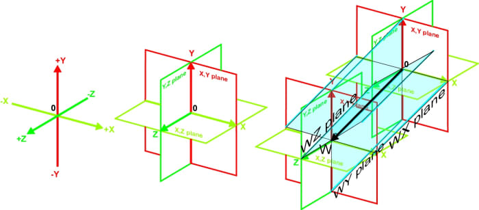
Fig. xx. Four-dimemsional coordinate organization
Fig. 21 shows the 4D tetrahedron, cube and octahedron drawn this way.
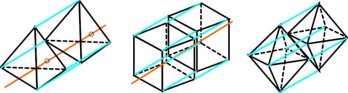
Fig. 21. Four-dimensional tetrahedron, cube and octahedron
By understanding these principles you lot can depict all sorts of 4D figures. These can be used to report and sympathize multiple-dimensional systems.
Fourdimensional on October 28, 2017:
Rotation in iv-dimensional space.
https://youtu.be/vN9T8CHrGo8
The 5-cell is an analog of the tetrahedron.
https://youtu.be/z_KnvGGwpAo
Tesseract is a four-dimensional hypercube - an analog of a cube.
https://youtu.be/HsecXtfd_xs
The xvi-cell is an analog of the octahedron.
https://youtu.be/1-oj34hmO1Q
The 24-cell is one of the regular polytope.
https://youtu.be/w3-TqPXKlVk
The hypersphere is an analog of the sphere.
Mara Alexander from Los Angeles, California on Feb 27, 2015:
So kewl, this is absolutely awesome. Thank you for sharing
I voted it upward
Bennimus - Standing on October 29, 2014:
I also forgot to mention. The connect-the-dots fob will work on cubes, just y'all can't use it on tetrahedrons. You will get a "tetrahedronal prism". A proper 5-prison cell has v vertices. Same for octohedrons. It Will NOT Piece of work unless you want to end up with a prism.
Bennimus on Oct 29, 2014:
About the 4D graph. In that location's a bit of a pattern in second representations of college-dimensional graphs.
Mostly, the Z axis goes upwards. In 2D drawings, Y goes upwardly. So where does Y go? Information technology gets squished downwards a little bit with the X centrality.
The same affair happens when nosotros introduce what's properly known as a W axis. When the West axis enters the scenario, It points up, and it squishes the Z axis alongside the Y and Ten axes.
All in all it really doesn't affair so long as you accept iv axes, only if you lot're always going to practise measurements of hypercubes, this is the easiest way to practice information technology.
Rahul on August 01, 2013:
Its actually so skilful, merely i know this, can y'all tell me something about 4-D sphere. My name is Rahul and my age is fourteen. If you lot can tell me something almost 4-D sphere than please tell me, this is my ID- planetchachi@gmail.com
Thanks Sir
Casper on December thirty, 2012:
Excellent!, nevertheless, a 4d tetrahedron has simply 5 corners!
In your example of a 4d tetrahedron you lot have made 2 normal tetrahedrons connected to each other bij 90 degree angles into the time.
Zack on February 29, 2012:
I could not exercise whatsoever of that! I'm simply in 7th class, and love math, and geometric shapes, but that fabricated no sense. Could you make that clearer, please? my electronic mail is lemanski_z@yahoo.com. Thx, Zack.
sve on February 20, 2012:
You fabricated it and then simple, it is genius. This is the best explanation of a Central Principle I have seen. Thanks. Continue going.
p johnny joe on November 22, 2011:
sir,it was awesome to run into 4 dimensional figure made by you,when it is going to come in to action,can we brand things useful to humanbeings by these figures,100% of the things are made up of 3dimensional,iam a mathematics teacher iam curious to know about information technology please write in particular to my id johnnyjoe2006@yahoo.com cheers
toxiKrystal on June 06, 2010:
very articulate and curtailed. suprising, because the amount of usefull informatin here, as well equally the complex nature of quaternary-dimentional space itself.
i caused useful knowledge and i am sure in that location is more to learn here. Bookmarked for sure ^-^
... aren't 4dimentional objects stunningly beautiful ^-^ you definitely aided my job of drawing them by hand.
much thanks
-krys
Mood on May 12, 2010:
Sir you lot are awesome and passionate, really benefited from this article, thank you and keep upward the awesome work coming !
tomlinsonmothe1966.blogspot.com
Source: https://feltmagnet.com/drawing/How-to-Draw-Four-Dimensional-Figures
Post a Comment for "how to draw a number 11 in 3d"